Version 1.0 | Last update: 11. November 2019
Stern Section
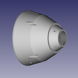
This section is accomodating our main propeller, rudder and dive fins.
1.
Stern section
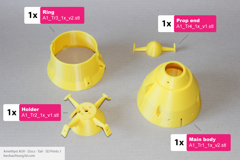
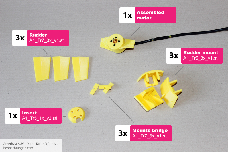
3D printed parts
All STL files are already oriented for generating g-code with your favorite software. Check part list on the right side of this page for best printing results.
2.
Stern section
Assembly parts
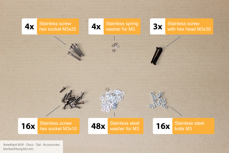
| How many | Type | Type note |
|---|---|---|
| 16x | M3x10 | Stainless steel hex socket head cap screw |
| 4x | M3x25 | Stainless steel hex socket head cap screw |
| 3x | M3x30 | Stainless steel screw with hex head |
| 16x | M3 bolt | Stainless steel |
| 48x | M3 washer | Stainless steel |
| 4x | M3 spring washer | Stainless steel |
3.
Stern section
Assembly
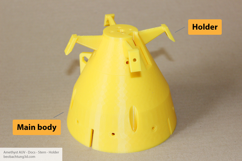
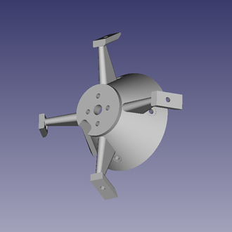
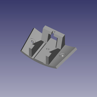
Connect ring holder with main body part together as showed.
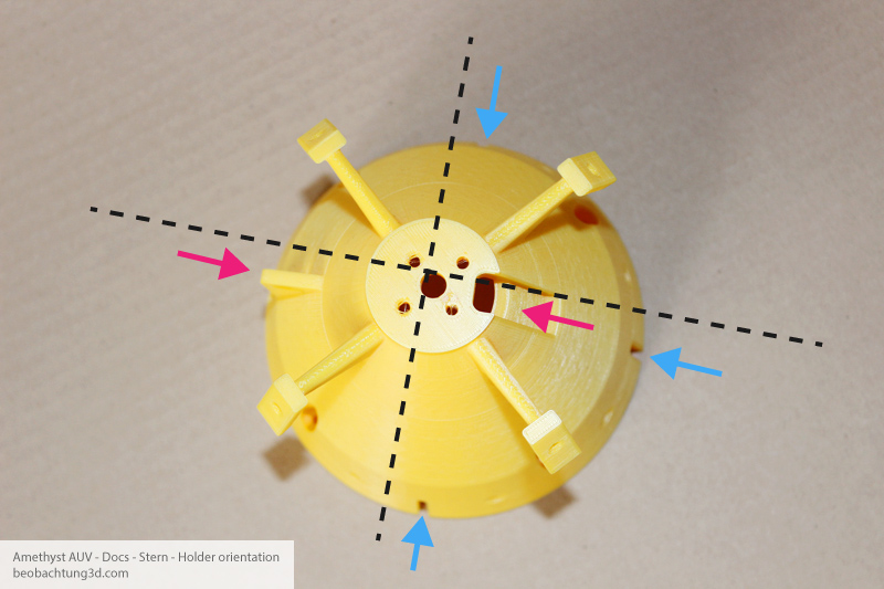
Be careful orintation of holder part. Hole for motor wires above shoud face eyelet at main body on oposite side (violet arrows). Notice orientation of main body cuts (blue arrows) against holder part.
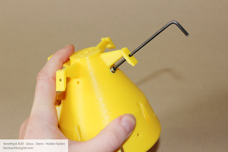
Use 4 M3x10 hex screws, 4 M3 bolts and 8 washers to unite both parts. You will find there is not much room inside the cone for work out the bolts. It needs a bit of skill and patience.
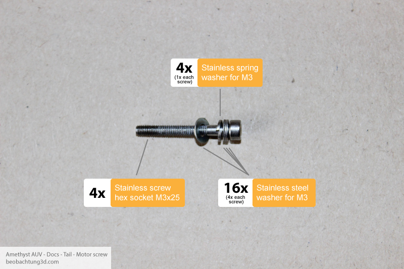
Prepare 4 M3x25 screws as showed above. We gonna use them to fasten motor with propeller to main body of stern part. Put spring washer between two classic washers. Watch out, screws should not go to fare in to motor to not damage winding inside, but do not screw them too shallow as well. Adjust that by adding or removing washers if advised number of 5 washers is not sufficient. Spring washers are needed certainly, they will help avoid unwanted relese of screws due vibrations of motor.
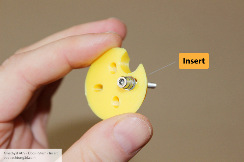
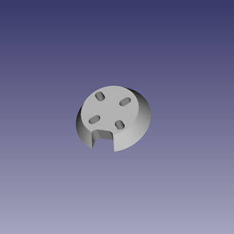
Insert prepared screws to all four holes in Insret part. Notice orientation of Insert part.
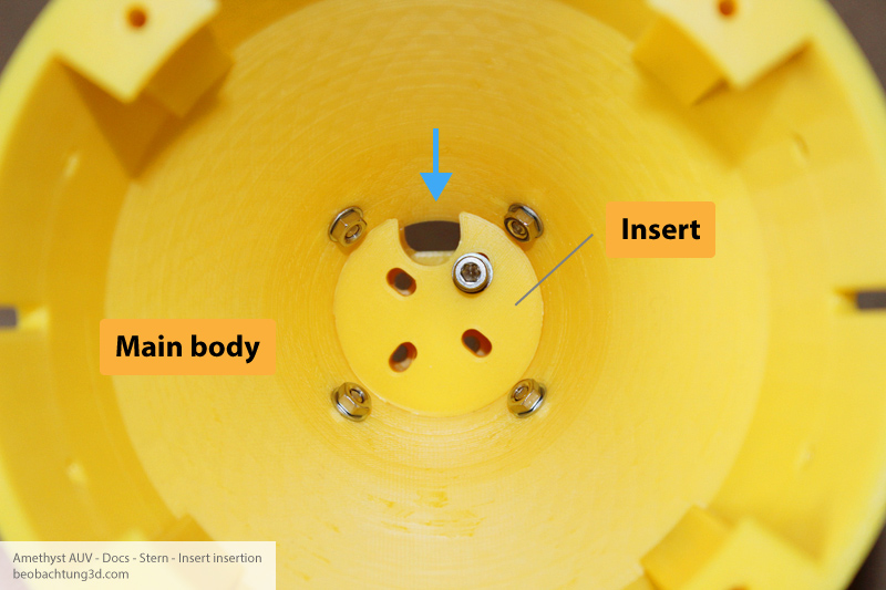
Push the screws with Insert part through the holes inside Main body part. Watch the orientation of the cut against hole of main part (blue arrow). You should already have a motor wire going through the hole and all four M3x25 screws with washers on place as can be seen on following image. This view without them is just for better visualisation of the mount.
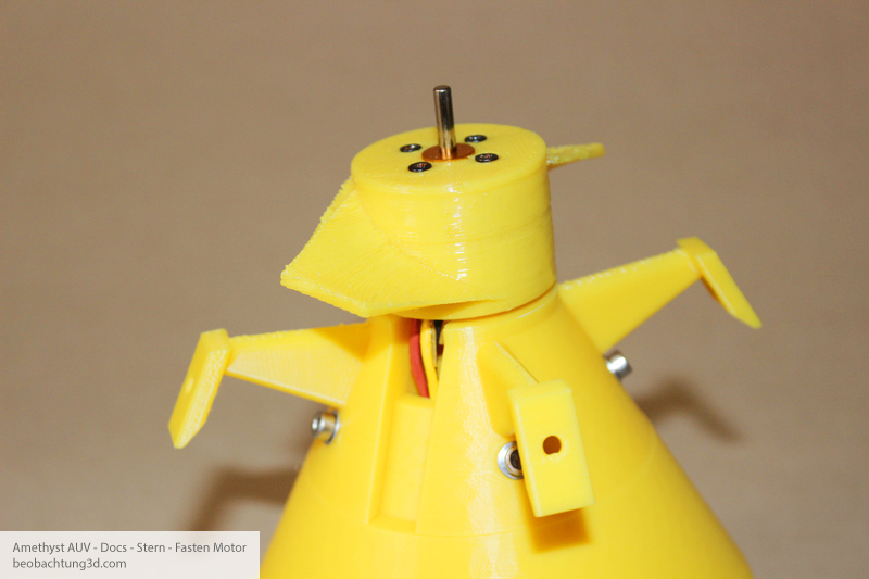
Fasten the screws from inside of main part. Motor with prop shoud look like this.
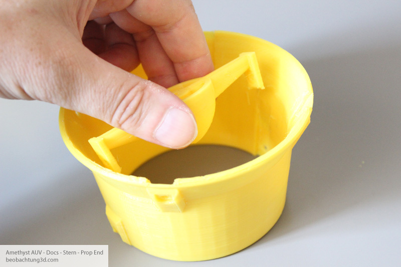
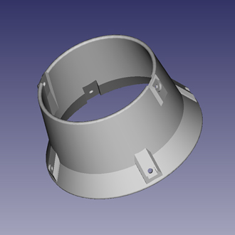
Put Prop End inside the ring fitting grooves.
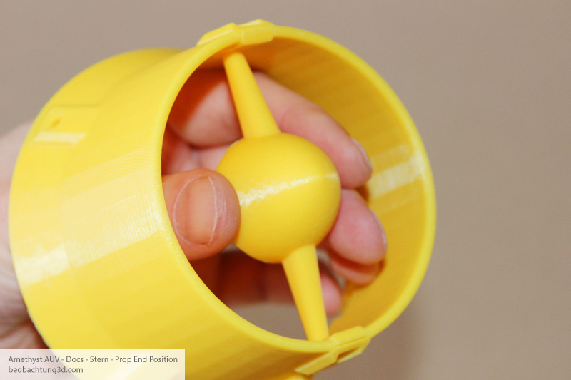
In to this position. And fasten srews. Don´t forget place washers under the srew heads and under the bolts as well.
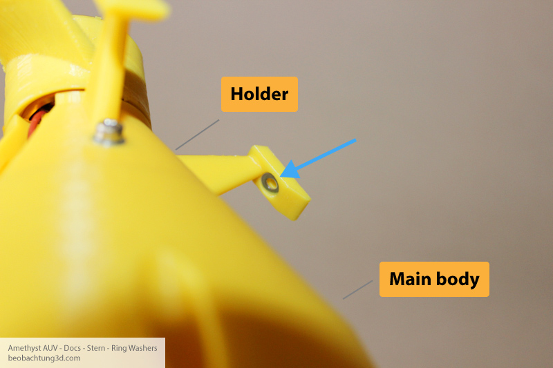
Impress washers in to holder´s arms first. It will ease work with bolts a bit.
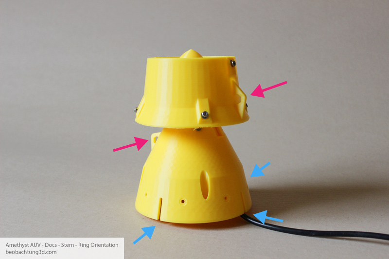
Then arrange ring to holder´s arms, place screws and fasten ring to main part. Ring´s eyelet must be on oposite side than eyelet at main body (purple arrows). Don´t forget place washers under screws heads.
4.
Stern section
Rudder and dive planes
1. Assembling dive planes and rudder mounts
Dive planes are incorporated with design mainly for AUV setups without vertical thrusters. But they could be used for depth correction in all AUV configurations. Using them is up to you, regarding your planed application.
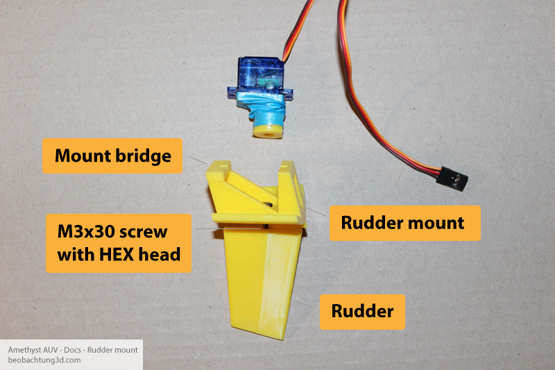
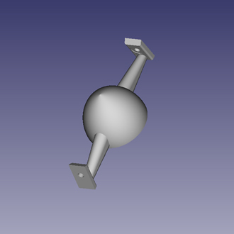
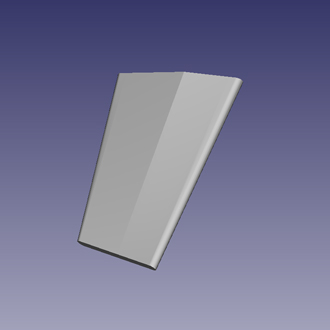
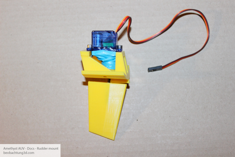
Prepare rudder and mount. Mount should look like this at the end.
[picture will be available soon]
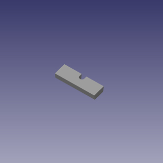
Glue the Rudder mount part with Mount bridge part as seen on picture. Notice orientation of bridge. Hole for screw shoud be orinted toward hole on bridge at the oposite side.
5.
Stern section
Attaching rudders
